
Water-supply design
Working out how much water a place needs, then designing what delivers it
A water supply is a chain: source, treatment, storage, network. It is sized from the demand a place will have, not from the distance the pipe has to run.
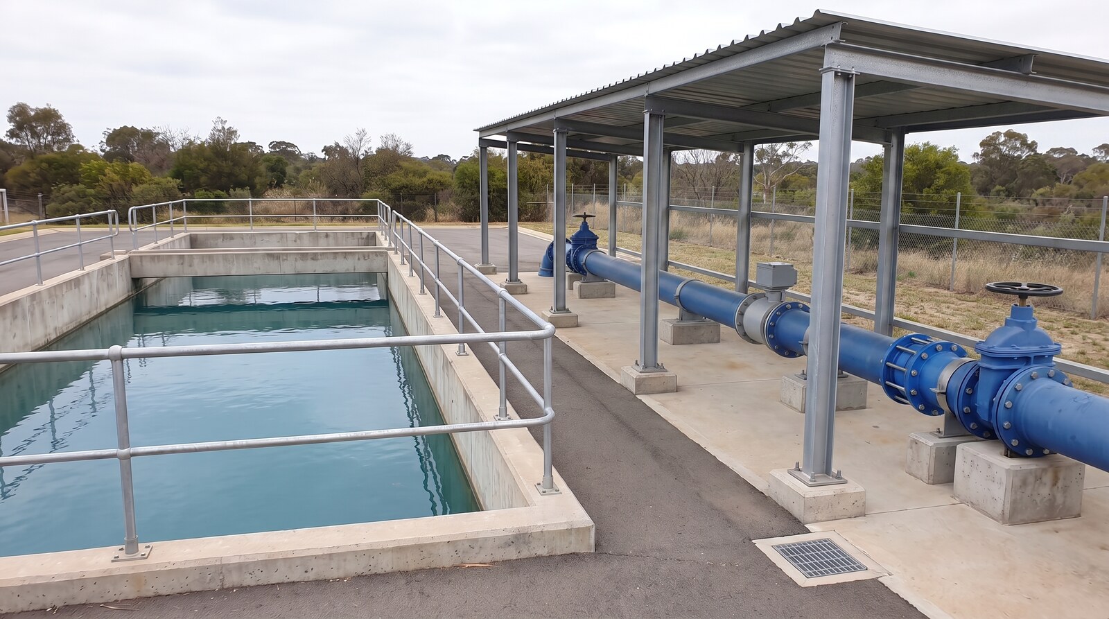
A chain that is only as good as its weakest link
A water-supply scheme has four parts that have to hold together end to end. A source that still yields enough in the driest month. Treatment that makes the raw water safe. Storage that carries the place through peak demand and pump downtime. And a distribution network that delivers usable pressure to the last connection on the line.
If any one of them is undersized, the failure shows up at the tap furthest from the reservoir, and it shows up years after the decision that caused it.
The counter-intuitive part is that distance does not set the pipe size. Distance costs head, and head is recovered with pumping or gradient. What sets the diameter is flow: how many litres per second the place will draw at its busiest hour, at the end of the design period. Get that single figure wrong and every decision downstream inherits the error.
When water-supply design is needed
Whether the scheme is municipal or private, the sizing question is the same one.
A new supply is being built
A town, a settlement or a development needs its own supply, and someone has to establish what it will draw before anything is specified.
An existing supply is failing
Pressure drops at the edges, the reservoir empties before the day is out, or growth has overtaken a network designed for a smaller population.
A scheme is being extended
New areas are being connected. Adding to a network changes its hydraulics everywhere, not only at the new end.
A facility needs process water
A plant or institution needs a supply sized to its own operation, with storage and pumping to match how it actually runs.
How a scheme is developed
Three stages, and the same demand figure has to survive all three unchanged.
Demand projection
Present population grown across the design horizon, multiplied by per-capita consumption, then lifted by peak-day and peak-hour factors and an allowance for losses.
Feasibility
Source yield tested against that demand, viable system options compared, and the information gaps that would otherwise undermine a design closed out.
Final design
One coordinated scheme: pipe diameters, pump duties, reservoir volumes, treatment process and the hydraulic grade line that ties them together.
Contract documentation
Drawings, specifications and bills of quantities precise enough for a contractor to price and build without guessing at the engineer’s intent.
What arrives, and what is needed to begin
You receive
A stated design basis with the demand projection and the assumptions behind it.
Hydraulic analysis: pipe sizing, pressures, pump duties and storage volumes.
Drawings, specifications and bills of quantities for construction.
A scheme whose capacities and quantities still describe the same project at tender as they did at feasibility.
To start, provide
The area to be served and its present population.
Records of the existing network, if there is one.
Source information and any yield or water-quality data already gathered.
Which part of the system is failing, if the scheme is an existing one.
Related work
Treatment structures, tanks and pipe crossings meet the structural discipline; access and crossings meet the transport one. Named water schemes are on the projects sheet.
Next step
A structure to design, a corridor to move a load along, or a build already on site?
That is a conversation worth having early, while the engineering decision can still be changed cheaply. Eng. Ombogo will say plainly where the work stands.